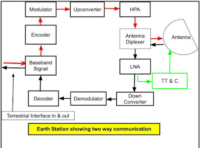
The above block diagram is explained below: Transmit chain: Terrestrial Network: The Earth station is connected to various terrestrial networks and a terrestrial network connected with exchanges and local exchanges. Local exchanges are connected with different modes of communication (voice, data, broadcast, internet etc.). Local exchanges multiplexed different types of signals as per need and compatibility to transmit to main exchanges. After multiplexing It may be 2mbps stream or otherwise. Main exchanges further multiplexed the signals as per requirement to transmit to Earth station.
Baseband Signal: The signal received from the terrestrial the network is processed at the Baseband signal unit. In this unit, received signal is demultiplexed, digitized (if it is not already digitized) and Other changes are made as per The need for the next unit i.e. Encoder. Output of the Baseband unit may be like 70 Mhz or 140 Mhz or as desired. Please keep in mind that The Baseband signal unit is the same for Transmission and Receiving the signal. Encoder: It introduces Error Correction Coding to reduce the error rate to the acceptable level. In this unit, extra bits are added to the signal received from Baseband unit to make the signal unique. These extra bits do not have any intelligence or information but Help us retrieve the signal at Receiver end. Modulator: The output of the Encoder is given to the modulator and here signal is modulated as per the need of earth station. In simple terms, modulation means the signal is imposed on the carrier Frequency.
Upconverter: Since modulation is generally done at 70 MHz or 140 MHz. You should Remember that modulation is always done at a lower frequency because These frequencies are most suitable for modulation and electronic components or devices are working well at lower frequencies. However for transmitting the signal from earth station to satellite, high frequency (minimum around 6 Ghz, if the satellite is working in C band) is required. High frequency carries high energy, and high energy is required to travel the large distance like 36000 Km for Geostationary satellites. Therefore Upconverter is employed Here to convert the frequency in 6 Ghz range or higher if the satellite is working in another frequency band like Ku. So here is the output of The modulator is mixed with local oscillator frequency to get the desired output. HPA: A High-power Amplifier (HPA) is employed here to amplify the signal up to that level which is suitable to reach the retrievable signal at satellite receive antenna. High-power amplifiers are generally TWTA (Travelling Wave Tube Amplifiers), however, these are now replaced by Solid State Power Amplifiers (SSPA). As the name suggests, these are capable of generating high power which is sufficient as needed.
Antenna Diplexer: The output of HPA is given to the Antenna Diplexer. Please keep in mind that Only one antenna is applied here which will handle transmission and Receive signals simultaneously. That is why Antenna Diplexer is needed here and it is capable of avoiding interference in between the outgoing and incoming signals. Antenna: The output of the Antenna diplexer goes to space through the antenna. This antenna may be a dish antenna or a specific antenna as needed. It is once again reiterated that the same antenna is being used for receiving the signal. One important fact is to be known to us i.e. Antenna beamwidth. Here we will not go into much depth, just try to understand what is Beam Width? Beamwidth means the solid conical angle made by the transmitted signal. Here, in this case, it should be a very narrow beamwidth to hit the satellite antenna perfectly without spillover the signal outside the satellite antenna.
Receive Chain: Antenna and Antenna Diplexer: As already mentioned in the transmit chain part that the Antenna and Antenna diplexer both are the same for the receive chain. Transmit and receive frequency is always kept different to avoid any interference in between the both, so the same antenna and antenna diplexer are working well for transmitting and receive chain. So the signal transmitted from a satellite is received here at the antenna and After passing through the antenna diplexer, the output is given to LNA. LNA: Low Noise Amplifier (LNA) is always mounted very near or at the feed of the antenna. Because the signal from The satellite is traveling a large distance like 36000 Km (if the satellite is working in Geostationary Orbit) Due to this long distance, The transmitted signal from the satellite suffer a heavy space loss and by reaching at the antenna of the Earth station, it becomes very feeble. If LNA is placed away from the antenna feed, then it is required to connect with some feeder wire which will again cause heavy loss to the received signal which is already feeble. So the signal may die out before reaching the LNA. Please keep in mind That feeder wire gives heavy loss on Ghz range frequency of satellite communication. As the name suggests, LNA is a special type of amplifier which will amplify the signal but not add or very negligibly add the noise generated by the LNA itself. If the simple amplifier is used at the place of LNA. It will add the self-generative noise with a feeble signal resulting in unretrievable signal.
Down Converter: The output of LNA is generally in Ghz range and for modulation, it should be around 70 Mhz or 140 Mhz. The reason for it is already explained in the transmit chain. Therefore the roll of the down converter is just the opposite of the Upconverter. Downconverters change the frequencies in the range of 70 Mhz or 140 Mhz or as desired. Demodulator: Its role is just opposite to Modulator. Here the signal is extracted from the downconverted carrier frequency to feed into the decoder. Decoder: The role of the Decoder is just the opposite of Encoder and it plays a very an important role in the extraction of real signals. Since the signal is traveling a long and passes through various processing units, due to this complex process, it is difficult to maintain the signal in 100% original form as transmitted. The extra bits added during the transmission at the encoder, help us To retrieve the signal correctly even if it is marginally corrupted during the process. So extra bits are added at the encoder end is removed here and the original signal is retrieved and sent to the Baseband signal unit.
Baseband Signal Unit: In this unit, the signal is further processed and multiplexed as per The need for the terrestrial interface and distributed to the terrestrial links accordingly. TT&C: Telemetry Tracking and command (TT&C) receives the input data and after amplification at LNA, it is sent back to the satellite. The counterpart of TT&C at Earth station also exists at the satellite end. TT & C at the satellite end checks the parameters of the satellite and sends it to the Control and Command center to correct it accordingly for proper Functioning of Satellite communication. In a nutshell, We can say that the role of TT&C ( at the earth station and on satellite) and Control and Command Centre is to maintain the good health of the satellite for its smooth functioning.
| 


.png)
Comments
Post a Comment
Thank you, most welcome, 👍